ARCH 655 Parametric Modeling in Design Project2 (Yang Shen)
ARCH 655 Parametric Modeling in Design Project2 (Yang Shen)
Part 1-Beijing Water Cube Sun Path and Radiation Analysis
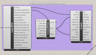
Sun Path Analysis
1. Import weather data
Radiation analysis and optimization
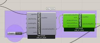
1. Set sky matrix
This step is to create the sky matrix profile which is the input data of radiation analysis.
(sky matrix)
2. Create the target building and context building
I just created outer box of Beijing Water cube as the target building. There are 4 parameters(genome) which are the length, width, height and orientation of building. The surrounding buildings are also created. The green building is the target building and red ones are the context buildings.
(target and context building)
3. Radiation analysis and optimizationThe total radiation is the fitness and 4 parameters mentioned before are the genome in the Galapagos. The optimized parameters are 40m, 40.341m, 40m and 104 degree of orientation. Because the ranges of length, width and height are set from 40m to 100m. To minimize the total radiation of this building, the geometry should be smallest one which makes sense.(optimization results in Galapagos)
Project2-Part1 YouTube Movie link: https://www.youtube.com/watch?v=pXEugCkt6E0
Part 2-Roof structural analysis
Introduction
(real structure)
(section view)
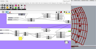
Step1-Create the geometry of structure
1. create midpoint of structure along the ellipse
Use 'ellipse' to create an ellipse with two parametric radius. By default, the original start-end point of ellipse cannot be changed, here by using 'seam' to change the start-end point by different degrees. This start-end point would be my structural mid point.
2. find the edge point of the structure by bay length and by numbers
3. get the base curve, cantilever curves and back span curve
(base curve, cantilever curves and back span curve)
4. create the main structural nodes
By using 'curve/plane intersection', the nodes of cantilever, back-span and backstay can be created. The end points of column can be also created.
(main structural nodes )
5. create the rafter mid points and rafter curves
The straight lines between cantilever nodes and back-span nodes are not what we want because the rafters should be curves. So I just extracted the mid points of straight lines and then move upwards to be real mid points of rafters. Now, using 'interpolate', we can create the rafter curves by three points.
6. create the purlin nodes and strut nodes
7. prepare all the structural lines.
After creating all the structural nodes, the structural lines can be created.
(structural lines)
Step2-assign the section properties for the structural lines
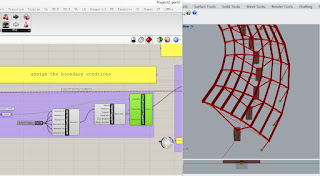
Step3-assign boundary conditions
Step4-assign static load on the nodes of purlins.
Step5-query node displacement
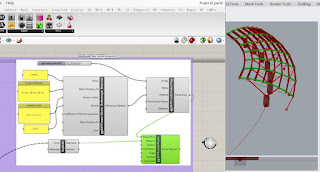
Step6-optimization
Project2-Part2 YouTube Movie link: https://www.youtube.com/watch?v=_bbk3rrIr7I&t=6s








Comments
Post a Comment